

This chapter records an example reference for a WLAN wireless LAN experiment in eNSP.
Topology and Requirements
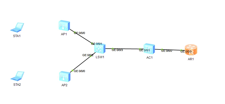
Requirements:
-
Basic Planning Step 1 VLAN deployment: Configure VLANs and Trunk on the switches and the AC. Step 2 IP address deployment: Configure IP addresses on the AC and R1. Step 3 Inter-VLAN routing deployment: Configure inter-VLAN routing on the AC, and appropriate routing tables on the AC and R1 so that the entire network can communicate. Step 4 DHCP service deployment: Deploy DHCP on the AC to provide IP addresses for the APs and wireless terminals.
-
Core Tasks Step 1 Create an AP group: Used to add all APs with the same configuration to the same AP group. Step 2 AP onboarding: Configure the AP authentication mode, add the AP to the group, power on the AP, and confirm that the AP finds the AC. Step 3 Configure WLAN service parameters: Configure the security template, SSID template, and VAP template. Step 4 Configure the AP radio channels and power: Configure the 2.4G and 5G radio channel and power optimization. The device interface connection planning table and the device interface IP address planning table are as follows.
Table 1 Switch VLAN planning and interface address table
| Device | VLAN ID | IP Address Range | VLAN Interface Address |
|---|---|---|---|
| S1 | VLAN100 | 10.23.100.0/24 | None |
| VLAN101 | 10.23.101.0/24 | None | |
| AC | VLAN100 | 10.23.100.0/24 | 10.23.100.1/24 |
| VLAN101 | 10.23.101.0/24 | 10.23.101.1/24 | |
| AP1 | VLAN1 | 10.23.100.0/24 | DHCP |
| AP2 | VLAN1 | 10.23.100.0/24 | DHCP |
Table 2 Switch VLAN planning and interface address table
| Device | Interface | Interface Type | VLAN | Peer Device and Interface |
|---|---|---|---|---|
| S1 | G0/0/1 | Trunk | VLAN100, 101 | AP G0/0/0 |
| G0/0/2 | Trunk | VLAN100, 101 | AP G0/0/0 | |
| G0/0/3 | Trunk | VLAN100, 101 | AC G0/0/1 | |
| AC | G0/0/1 | Trunk | VLAN100, 101 | S1 G0/0/3 |
| G0/0/2 | Trunk | VLAN101 | R1 G0/0/0 | |
| R1 | G0/0/0 | Trunk | VLAN101 | AC G0/0/2 |
| LookBack10 | ||||
| AP1 | G0/0/0 | S1 G0/0/1 | ||
| AP2 | G0/0/0 | S1 G0/0/2 | ||
| STA1 | Wireless interface | AP1 | ||
| STA2 | Wireless interface | AP2 |
Table 3 Device interface IP address planning table
| Device | Interface | IP Address | Remarks |
|---|---|---|---|
| S1 | VLAN100 | None | |
| VLAN101 | None | ||
| AC | VLAN100 | 10.23.100.1/24 | |
| VLAN101 | 10.23.101.1/24 | ||
| R1 | G0/0/0.101 | 10.23.101.2/24 | VLAN101 sub-interface |
| LookBack10 | 10.10.10.10/24 | ||
| AP1 | VLANIF 1 | DHCP | Gateway: 10.23.100.1 |
| AP2 | VLANIF 1 | DHCP | Gateway: 10.23.100.1 |
| STA1 | Wireless interface | DHCP | Gateway: 10.23.101.1 |
| STA2 | Wireless interface | DHCP | Gateway: 10.23.101.1 |
Table 4 Direct-connect layer-2 networking AC data planning table
| Configuration Item | Data |
|---|---|
| AP management VLAN | VLAN 100 |
| STA service VLAN | VLAN 101 |
| DHCP server | The AC acts as the DHCP server to assign IP addresses to the APs and STAs |
| AP IP address pool | 10.23.100.2~10.23.100.254/24 |
| STA IP address pool | 10.23.101.3~10.23.101.254/24 |
| AC source interface IP address | VLANIF 100: 10.23.100.1/24 |
| AP group | Name: ap-group1 Referenced templates: VAP template wlan-net, domain management template default |
| Domain management template | Name: default Country code: China |
| SSID template | Name: wlan-net SSID name: wlan-net |
| Security template | Name: wlan-net Security policy: WPA-WPA2+PSK+AES Password: a1234567 |
| VAP template | Name: wlan-net Forwarding mode: Direct forwarding Service VLAN: VLAN 101 Referenced templates: SSID template wlan-net, security template wlan-net |
Experiment Steps
IP Configuration
Skipped
R1:
sys
sys R1
un in en

int g0/0/0.101
dot1q termination vid 101
//Indicates packets will be forwarded at Layer 3 with the VLAN tag removed. When sending packets, the corresponding VLAN tag is also added; here VID100 is written, so outgoing packets carry the VLAN 100 tag

ip add 10.23.101.2 24
arp broadcast enable
//The sub-interface does not have ARP broadcast capability by default, so ARP broadcast must be enabled here
quit
int lo10
ip add 10.10.10.10 24
quit
Static Routing
[AC]ip route-static 0.0.0.0 0.0.0.0 10.23.101.2
[R1]ip route-static 10.23.100.0 255.255.255.0 10.23.101.1
Configure DHCP
AC:
dhcp enable

int vlan100
dhcp select interface
quit
int vlan101
dhcp select interface
dhcp server excluded-ip-address 10.23.101.1 //Exclude this IP
dhcp server dns-list 10.10.10.10 //Specify the DNS as AR LookBack10 as required
quit
Configure AP
AC:
wlan //Enter the WLAN configuration panel

ap-group name ag1 //Define the AP group name: ag1
quit

regulatory-domain-profile name default //By default, the AP group references a domain management template named default
country-code cn //Specify the AC country code as China
quit

ap-group name ag1
regulatory-domain-profile default //This references the default management template within the AP group
quit
Bring the AP Online
[AC]capwap source interface vlanif 100
//Configure the source interface of the AC
wlan
ap auth-mode mac-auth //Configure the AP authentication mode
ap-id 0 ap-mac 00E0-FC84-2220 //Each AP is different, check it yourself
ap-name ar1 //Literally the name
ap-group ag1 //Add it to the ag1 group
(Press Y to confirm)
Warning: This operation may cause AP reset. If the country code changes, it will clear channel, power and antenna gain configuration
s of the radio, Whether to continue? [Y/N]:Y

quit

ap-id 1 ap-mac 00E0-FCDE-24D0 //Each AP is different, check it yourself
ap-name ar2
ap-group ag1
(Press Y to confirm)
......omitted...Whether to continue? [Y/N]:Y
quit
Command to check whether the AP is online: dis ap all
[AC-wlan-view]**display ap all**

Info: This operation may take a few seconds. Please wait for a moment.done.

Total AP information:

nor : normal     [2]

\---------------------------------------------------------

ID  MAC      Name  Group   IP      Type      State STA Upt

ime

\--------------------------------------------------------------------------------------------------

0  00e0-fc4f-3de0 area_1 ap-group1 10.23.100.239 AP5030DN    nor  1  1H:10M:48S

1  00e0-fc3e-2040 area_2 ap-group1 10.23.100.6  AP5030DN    nor  1  1H:10M:39S

\----------------------------------------------------------------------
AP state nor: the AP is online.
AP state idle: the AP is idle and suspended, it cannot be recognized, and a connection cannot be established. It is recommended to stop the AP and retry, or reconfigure the AC and configure the AP-MAC while the AP is offline.
For other states, refer to the Huawei official manual for hints.
Configure WLAN Service Parameters
//Configure the security policy with WPA-WPA2+PSK+AES authentication and password "a1234567"
[AC]wlan
[AC-wlan-view]security-profile name wlan-net
[AC-wlan-sec-prof-wlan-net]security wpa-wpa2 psk pass-phrase a1234567 aes
[AC-wlan-sec-prof-wlan-net]quit

//Create an SSID template named wlan-net; the SSID name is what STAs scan for
[AC-wlan-view]ssid-profile name wlan-net
[AC-wlan-ssid-prof-wlan-net]ssid wlan-net
[AC-wlan-ssid-prof-wlan-net]quit

/Create the WLAN VAP template, configure direct forwarding mode, service VLAN 101, and reference the security template and SSID template
[AC-wlan-view]vap-profile name wlan-net
[AC-wlan-vap-prof-wlan-net]forward-mode direct-forward
[AC-wlan-vap-prof-wlan-net]service-vlan vlan-id 101
[AC-wlan-vap-prof-wlan-net]security-profile wlan-net
[AC-wlan-vap-prof-wlan-net]ssid-profile wlan-net
[AC-wlan-vap-prof-wlan-net]quit

//Reference the VAP template; on the AP, both radio 0 and radio 1 use the "wlan-net" configuration of the VAP template
[AC-wlan-view]ap-group name ap-group1
[AC-wlan-ap-group-ap-group1]vap-profile wlan-net wlan 1 radio 0
[AC-wlan-ap-group-ap-group1]vap-profile wlan-net wlan 1 radio 1
[AC-wlan-ap-group-ap-group1]quit


//Configure the two radios: AP radio 0 is the 2.4GHz radio, and radio 1 is the 5GHz radio.
//Configure AP1 radio 0 with channel 6, 20MHz bandwidth, and 127mW power
[AC-wlan-view]ap-id 0
[AC-wlan-ap-0]radio 0
[AC-wlan-radio-0/0]channel 20mhz 6
Warning: This action may cause service interruption. Continue?[Y/N]y
[AC-wlan-radio-0/0]eirp 127
//Also configure the channel and power of AP radio 1
[AC-wlan-ap-0]radio 1
[AC-wlan-radio-0/1]channel 20mhz 149
Warning: This action may cause service interruption. Continue?[Y/N]y
[AC-wlan-radio-0/1]eirp 127
[AC-wlan-radio-0/1]quit

//Configure AP2 channel as 11. This experiment requires: 2.4G AP1 channel 6 and AP2 channel 11; 5G AP1 channel 149 and AP2 channel 153.
[AC-wlan-view]ap-id 1
[AC-wlan-ap-1]radio 0
[AC-wlan-radio-1/0]channel 20mhz 11
Warning: This action may cause service interruption. Continue?[Y/N]y
[AC-wlan-radio-1/0]eirp 127
[AC-wlan-radio-1/0]quit
//Also configure the channel and power of AP radio 1.
[AC-wlan-ap-1]radio 1
[AC-wlan-radio-1/1]channel 20mhz 153
Warning: This action may cause service interruption. Continue?[Y/N]y
[AC-wlan-radio-1/1]eirp 127
[AC-wlan-radio-1/1]quit
Project Verification
display vap ssid wlan-net When the "Status" field shows "ON", it indicates that the VAP on the corresponding radio of the AP has been created successfully.
Try connecting an STA and check the IP address to verify it.
Key Knowledge Points
dhcp select ?
Router-Vlanif1] dhcp select interface
This means the interface IP is used as the gateway. For example, if your VLANIF IP is 192.168.100.1, then the PC below obtains 192.168.100.254 as its address and 192.168.100.1 as its gateway.

[Router-Vlanif1]dhcp select global
This makes DHCP select the global address pool. In this case you need to define a DHCP pool, and configure the gateway and so on yourself.
regulatory-domain-profile
Specify a template to reference it on an AP or AP group.
Click for details: Official explanation
capwap source interface ?
Specifies the AC source interface. Click for details: Official explanation
ap auth-mode ?
AP authentication mode; there are MAC, SN, and other methods. For details, see: Official explanation
ap-group ?
In the AP view, it is used to join a certain AP group.
Example:
ap-id 0 ap-mac 00E0-FC84-2220 //Each AP is different, check it yourself
ap-name ar1 //Literally the name
ap-group ag1 //Add it to the ag1 group
In the WLAN view, it is used to create an AP group.
Example:
wlan //Enter the WLAN configuration panel

ap-group name ag1 //Define the AP group name: ag1
forward-mode ?
Forwarding mode configuration. For details, see: Official explanation
Wireless AP Channel (Channel)
Because signal coverage overlaps, according to the channel rule: the 2.4G channel (radio 0) values of adjacent APs should be spaced 5 (inclusive) or more apart, and the 5G channel (radio 1) values of adjacent APs should be spaced 4 (inclusive) or more apart.
For details, Baidu it.
If you enjoyed this, leave a comment~