

This chapter records a reference for the basic VlanMapping experiment configuration.
Topology and Requirements
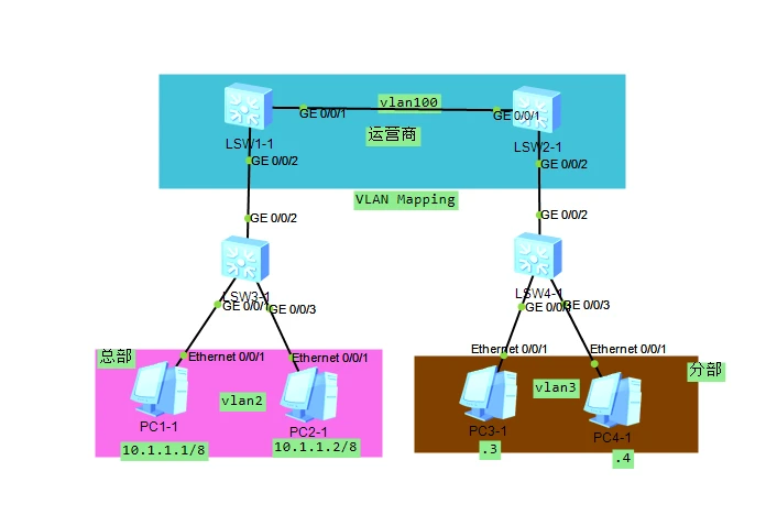
Requirements:
Complete the VLAN mapping of VlanMapping
Enable PCs in different VLANs to communicate with each other
Reference Configuration
- LSW3-1
[Huawei]int g0/0/2
[Huawei-GigabitEthernet0/0/2]dis th
#
interface GigabitEthernet0/0/2
 port link-type trunk
 port trunk allow-pass vlan 2

[Huawei-GigabitEthernet0/0/2]int g0/0/1
[Huawei-GigabitEthernet0/0/1]dis th
#
interface GigabitEthernet0/0/1
 port link-type access
 port default vlan 2

[Huawei]int g0/0/3
[Huawei-GigabitEthernet0/0/3]dis th
#
interface GigabitEthernet0/0/3
 port link-type access
 port default vlan 2
- LSW4-1
[Huawei]int g0/0/2
[Huawei-GigabitEthernet0/0/2]dis th
#
interface GigabitEthernet0/0/2
 port link-type trunk
 port trunk allow-pass vlan 3

[Huawei-GigabitEthernet0/0/2]int g0/0/1
[Huawei-GigabitEthernet0/0/1]dis th
#
interface GigabitEthernet0/0/1
 port link-type access
 port default vlan 3

[Huawei]int g0/0/3
[Huawei-GigabitEthernet0/0/3]dis th
#
interface GigabitEthernet0/0/3
 port link-type access
 port default vlan 3
- LSW1-1
[S1]int g0/0/1
[S1-GigabitEthernet0/0/1]dis th
#
interface GigabitEthernet0/0/1
 port link-type trunk
 port trunk allow-pass vlan 100

[S1-GigabitEthernet0/0/1]int g0/0/2
[S1-GigabitEthernet0/0/2]dis th
#
interface GigabitEthernet0/0/2
 qinq vlan-translation enable
 port link-type trunk
 port trunk allow-pass vlan 2 100
 port vlan-mapping vlan 2 map-vlan 100
- LSW2-1
[S1]int g0/0/1
[S1-GigabitEthernet0/0/1]dis th
#
interface GigabitEthernet0/0/1
 port link-type trunk
 port trunk allow-pass vlan 100

[S1-GigabitEthernet0/0/1]int g0/0/2
[S1-GigabitEthernet0/0/2]dis th
#
interface GigabitEthernet0/0/2
 qinq vlan-translation enable
 port link-type trunk
 port trunk allow-pass vlan 3 100
 port vlan-mapping vlan 3 map-vlan 100
Knowledge Points
Hosts in VLAN 2 at the head office and hosts in VLAN 3 at the branch office access each other through VLAN Mapping technology. After VLAN 2-to-VLAN 100 mapping is configured on interface G0/0/2 of S1, when the interface sends VLAN 2 frames outward, it replaces the VLAN Tag 2 in the frames with 100; when it receives VLAN 100 frames, it replaces the VLAN Tag 100 in the frames with 2, and then forwards the data according to the Layer 2 forwarding process. Similarly, VLAN 3-to-VLAN 100 mapping is configured on interface G0/0/2 of S2, so that VLAN 2 and VLAN 3 can communicate with each other.
Command Explanation
qinq vlan-translation enable
 // enable the VLAN translation function
  port vlan-mapping vlan 2 map-vlan 10
  // configure VLAN10 to map to VLAN10
Note
Note:
The VLAN ID of the VLAN Tag carried by frames received on an interface cannot be the same as the VLAN ID of the VLAN Tag after mapping.
The outer VLAN after mapping must exist, and the interface must join the VLANs before and after mapping in Tagged mode.
VLAN Stacking and VLAN Mapping can take effect simultaneously, but the VLAN IDs of multiple CEs configured at the same time cannot be duplicated, and the VLAN IDs of the VLAN Tags before and after mapping cannot duplicate them either. The same requirement applies to the VLAN ID configuration of PEs.
On Layer 2 Ethernet interfaces, only VLAN ID-based VLAN Mapping is supported; VLAN Mapping based on 802.1p or a combination of VLAN ID + 802.1p priority is not supported.
Multiple instances of this command can be configured on an interface, and up to 128 VLAN Mapping entries in total can be configured across all interfaces.
If you enjoyed this, leave a comment~