

This chapter records a small assignment experiment on VLAN aggregation, namely SuperVlan.
Topology and Requirements
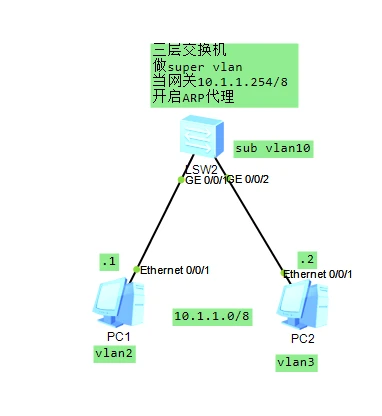
Requirements: Use Layer 3 switch technology to enable hosts to communicate across different VLANs Enable ARP proxy under mutual isolation to achieve Layer 3 communication
Reference Configuration
-
IP configuration is omitted
-
SW1
[S1]vlan batch 2 to 3 10
[S1]vlan 10
[S1-vlan10]aggregate-vlan
[S1-vlan10]access-vlan 2 to 3
[S1]interface Vlanif10
[S1-Vlanif10]ip address 10.1.1.254 255.255.255.0
[S1-Vlanif10]arp-proxy inter-sub-vlan-proxy enable
[S1]interface GigabitEthernet0/0/1
[S1-GigabitEthernet0/0/1]port link-type access
[S1-GigabitEthernet0/0/1]port default vlan 2
[S1]interface GigabitEthernet0/0/2
[S1-GigabitEthernet0/0/2]port link-type access
[S1-GigabitEthernet0/0/2]port default vlan 3
Knowledge Points
SUPER VLAN is also known as VLAN Aggregation.
Its principle is that one SUPER VLAN contains multiple SUB VLANs, and the SUPER VLAN can be configured with the IP address of a virtual interface.
Each SUB VLAN is a broadcast domain. Different SUB VLANs are Layer 2 isolated from each other, and SUB VLANs cannot be configured with virtual interface IP addresses.
When users within a SUB VLAN need Layer 3 communication, the IP address of the SUPER VLAN's virtual interface is used as the gateway address, so multiple VLANs share one IP address, thereby saving IP address resources.
At the same time, to achieve Layer 3 intercommunication between different SUB VLANs and between SUB VLANs and other networks, the ARP proxy function is required.
Through ARP proxy, ARP request and response packets can be forwarded and processed, thereby achieving Layer 3 intercommunication between Layer 2 isolated ports. By default, the ARP proxy function on a SUB VLAN is disabled.- Initially, Layer 3 communication fails because in different VLANs, ARP cannot reach across.
- Enabling PC1 to obtain PC2's MAC address is exactly what ARP proxy does. Example: arp-proxy inner-sub-vlan-proxy enable
- The process is as follows:
Communication between different VLANs in the same subnet
PC1-----Gateway------PC2
1. PC1 sends an ARP request (destination IP: PC2) ------- received by the gateway
2. After receiving it, the gateway also sends an ARP request (broadcast) with destination IP: PC2 ----- PC2 receives it
3. PC2 replies to the gateway with a unicast ARP response (IP: PC2, MAC: PC2)
4. The gateway replies to PC1 with a unicast ARP response (IP: PC2, MAC: Gateway)-
After ARP proxy is configured, the two PCs can communicate with each other while Layer 2 isolated.
-
Main SuperVLAN configuration
/Configure super VLAN
system-view
vlan 3
supervlan           //Define the super VLAN
quit

vlan 33
port ethernet3/1/3  //Define the port that belongs to the sub VLAN
quit

vlan 3
subvlan 33          //Define the mapping between the super VLAN and the sub VLAN

vlan 33
arp proxy enable    //Enable the ARP proxy function on the sub VLAN
Notes
Note:
A super VLAN cannot contain ports
After a VLAN is set as a super VLAN, the ARP proxy on that VLAN interface is automatically enabled and requires no configuration
While the super VLAN exists, the ARP proxy on its corresponding VLAN interface cannot be disabled. The default VLAN cannot be created as a super VLAN. Multiple ports (non-uplink ports) can be added to each sub VLAN
A sub VLAN cannot be configured with a virtual interface. The undo subvlan vlan-id command, when issued without a vlan-id, removes the mapping between all sub VLANs and the specified super VLAN; when issued with a vlan-id, it removes the mapping between the specified sub VLAN and the specified super VLAN.
Please do not enable multicast VLAN or igmp-snooping under a super VLAN.
xxxxxxxxxx Note: The VLAN ID of the VLAN Tag carried in frames received on an interface cannot be the same as the VLAN ID of the VLAN Tag after mapping. The outer VLAN after mapping must exist, and the interface must join the VLANs before and after mapping in Tagged mode. VLAN Stacking and VLAN Mapping can take effect simultaneously, but the VLAN IDs of multiple CEs configured at the same time must not be duplicated, and the VLAN IDs of the VLAN Tags before and after mapping must not duplicate them either. The same requirement applies to PE VLAN ID configuration. Layer 2 Ethernet interfaces support only VLAN ID-based VLAN Mapping, not VLAN Mapping based on 802.1p or VLAN ID + 802.1p priority. Multiple instances of this command can be configured on an interface, and up to 128 VLAN Mapping entries can be configured across all interfaces. text
- Example of super VLAN configuration: Create super VLAN 10 and sub VLANs: 2, 3, 5. Ports 1 and 2 belong to VLAN 2; ports 3 and 4 belong to VLAN 3; ports 5 and 6 belong to VLAN 5. Since Layer 2 isolation is satisfied between VLANs, Layer 3 intercommunication is now required between every pair of sub VLANs.
system-view
vlan 10
super vlan

vlan 2
port ethernet3/1/1 ethernet3/1/2
arp proxy enable

vlan 3
port ethernet3/1/3 ethernet3/1/4
arp proxy enable

vlan 5
port ethernet 3/1/5 ethernet3/1/6
arp proxy enable

vlan 10
subvlan 2 3 5

interface vlan 10
ip address 10.110.1.1 255.255.255.0
If you enjoyed this, leave a comment~